 [STRAUS Applications] [STRAUS Specifications]
[STRAUS Users Page] [STRAUS Model Archive] [Technical Papers and Tips Contents Page]
[Technical Articles Contents Page] [Home Page] [Previous Page] [Next Page]
 [STRAUS Applications] [STRAUS Specifications]
[STRAUS Users Page] [STRAUS
Model Archive] [Technical Papers and Tips
Contents Page]
[Technical Articles
Contents Page] [Home Page] [Previous
Page] [Next Page]

Following is a short discussion on some of the problems that can arise and some recommended modelling techniques.
Stiffened plates are common in all types of engineering design and common examples include concrete slabs with beam stiffeners and aluminium aircraft structures that comprise a thin skin stiffened by stringers. Examples of both of these structures are shown in the figure below. There are many methods that can be used to model stiffened plates. The one that is chosen will depend on the type of structure, the information required from the model, etc. Following is a brief look at some of the more common methods and a note about their advantages, disadvantages and problems that can occur.
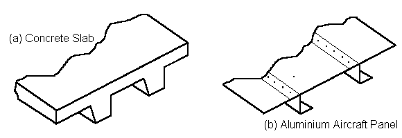
Typical Stiffened Panels
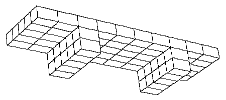
Brick model
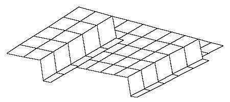
Plate model
Orthotropic structures can have different stiffness in each of the two principal directions and the membrane and bending stiffness can be independent of one another. To specify the orthotropic characteristics for a stiffened panel the [C] and [D] matrices must be calculated and then input into the orthotropic plate properties. The STRAUS manual contains information on calculating these [C] and [D] matrices. Reinforced concrete is a special type of stiffened panel that is sometimes modelled using orthotropic plate properties. This allows the contribution of the steel to the stiffness to be modelled more accurately.
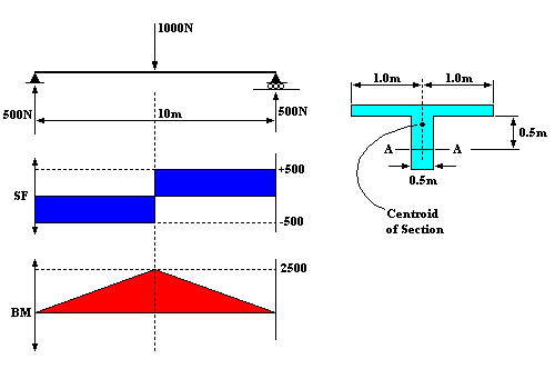
Example - Consider the centrally loaded, simply supported beam shown in figure below.
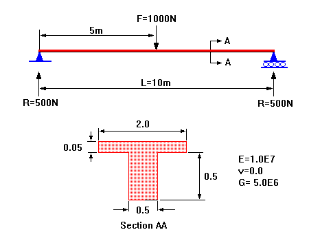
Simply supported beam.
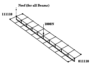
This will be modelled with a plate offset beam combination and various aspects of the modelling and results will be discussed. Following is an analysis of this beam by (a) a conventional manual method and (b) by STRAUS using a combination of plates and offset beams.
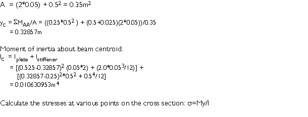
Hand Calculation - Theoretical Results
| 1. | Bottom of Beam | |
| S1 = (2500*0.32875)/0.010630953 | = 77309 Pa | |
| 2. | Centroid of Beam | |
| S2 = (2500*(0.32875-0.25))/0.010630953 | = 18519 Pa | |
| 3. | Top of Beam/Bottom of Plate | |
| S3 = (2500*(0.5-0.32875))/0.010630953 | =-40271 Pa | |
| 4. | Centroid of Plate | |
| S4 = (2500*(0.525-0.32875))/0.010630953 | =-46150 Pa | |
| 5. | Top of Plate | |
| S5 = (2500*(0.55-0.32875))/0.010630953 | =-52029 Pa | |
| The Deflection at the centre of the beam is: | ||
| y = PL3/48EI | ||
| = (1000*103)/(48*1.0E7*0.010630953) | ||
| = 0.195968634m |
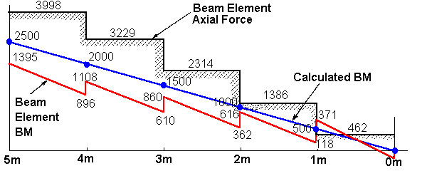
Shear Force and Bending Moment Diagram for one symmetric side only.
Finite Element Results

Displacements - The vertical deflection of the node to which the force is applied is 0.2016 (error 2.87%)
| Stresses | Error (%) | (%) | |
|---|---|---|---|
| 1. | Bottom of Beam | S1 = 82950 Pa | 7.39 |
| 2. | Centroid of Beam | S2 = 15992 Pa | 13.65 |
| 3. | Top of Beam | S3 = -50960 Pa | 26.54 |
| Bottom of Plate | S3 = -37872 Pa | 5.96 | |
| 4. | Centroid of Plate | S4 = -44503 Pa | 3.57 |
| 5. | Top of Plate | S5 = -51135 Pa | 1.72 |
Deflection - The deflection predicted by the STRAUS model is approximately 2.87% too large. This is an acceptable error for this model.
Shear Force and Bending Moments - In both cases the bending moments are plotted in the graph above; in the first case (a) for the complete beam by the consideration of equilibrium of external and internal forces; in the second case (b) the moments in the offset beam are plotted. Some STRAUS users have assumed that this will represent the bending moment of the beam as a whole. Clearly this is not the case. The peak bending moment obtained from the hand analysis is 2500 Nm compared with only 1395 Nm for the beam element in the finite element model. In this case the beam and the plate elements work together to carry the moment since the finite element model must be in equilibrium at any point with the external applied loads.
The forces acting on the elements at any section through the beam are as follows:
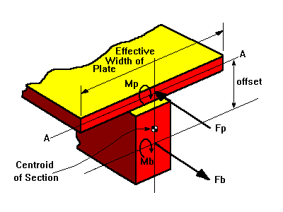
The sum of the forces and moments at this section must equal the forces and moments due to the externally applied loads. For convenience the sum of the moments can be taken about the mid plane of the plate; this effectively removes the plate membrane stress from the calculation. So the sum of the moments is as follows:
SMAA=0=(Fb*Offset)-Mb-Mp=Msection
Obviously the signs of the forces, moments etc. will depend on each individual problem and the orientation of the plates and beams.
In many such problems the moment in the plate is small and can be neglected. However it is suggested that users intending to do modelling of this type carry out their own tests on a model representative of their structure to verify this assumption. It is fortunate if the plate bending moment can be neglected as it can be very difficult to get these moments from the model if the geometry is not regular or the structure is not aligned with the global axis system. STRAUS outputs moments in the global axis system at the element centroids - these will not correspond to the beam axis in many cases.
From this summation of moments it is clear that the moment due to the externally applied forces is balanced by the bending moment in the beam element plus the couple due to the axial force in the beam times the offset. Any beam design will have to consider this total moment. There are two distinct types of structures that we have to consider:
(i) In the case of a structure where the plate sits on but is not rigidly connected to a beam then the beam will have to be designed to carry the total moment. It should be noted that the moment obtained from the finite element model will be independent of the section of the beam included in the model. The offset beam approach should not really be used to model structures of this type since this method assumes that the beams are rigidly connected to the plates. For a further discussion of a technique that can be used in this situation see Section 6 below.
(ii) In the second case where a stiffener is rigidly attached to the plate as in the case of a concrete slab with an integral stiffener then the design would be approached differently. This problem is similar to the one shown in the previous example. For this case it is inappropriate to attempt to design the plate and the beam individually. It will be necessary to assume that the stiffener beam acts together with an effective section of the plate to resist the total bending moment. How much of the plate is assumed effective in resisting bending will depend on the particular application, the engineering discipline and in some cases the codes in use. The most conservative assumption would be to take only the section of plate to which the beam connects as being effective. In other not so conservative applications such as aeronautical applications it is common to assume that a considerable section of the plate either side of the stringer is also effective in resisting the bending. Whatever section is chosen it will be necessary to extract the total moment on the section using the above method and check the bending of the beam by manual calculation. This may sound time consuming but in most cases only a few sections will have to be considered. Since many beams are essentially constant in cross section, only the locations of peak moment will need to be checked. In any case the stresses in the finite element model will be approximately correct and these can be used as a guide to the locations that need detailed investigation.
It is evident from looking at the bending moment diagram for the beam element in the previous example that this is not continuous - it has a pronounced saw tooth pattern. It is obvious that this does not represent the physical situation as the bending moments must be continuous in any real structure. This characteristic of the bending moments in offset beams has prompted several questions from STRAUS users. The reason for this is not obvious; to gain an understanding of the reasons behind this it is necessary to study the forces in the various elements.
In any given beam element the axial force must be constant whilst the bending moment can vary linearly. Additional loads can only be transferred to the beam elements at the nodal points. Now the externally applied bending moment varies linearly and according to the above equation for the summation of moments, if the bending moment in the beam elements is to be also continuous across adjacent elements then the beam axial force would also have to vary linearly. Since the axial force in the beam elements is a constant stepwise approximation to the linear variation that would be expected in practice, it follows that the bending moment in the beam element must also be a discontinuous approximation.
What all this is saying is that the axial force and hence the beam element bending moment are correct at only one point on the element - the centre; this is the only point on the beam element for which the axial force will equal that in the real structure. At any other point the distribution of forces and moments will be an approximation necessary to ensure the overall equilibrium of the beam at that cross section with the external forces.
In the particular example above the axial force is too low at the ends of the elements closest to the centre of the beam model and too high at the ends closest to the supports. Hence it follows from the above equation for moment equilibrium that the moments will be too low at the ends of the elements closest to the centre of the beam model and too high at the ends nearest the supports. This explains the discontinuity in the moments between adjacent beams - the step change in axial force at the nodes requires a step change in moment to ensure equilibrium at the node.
Nodal equilibrium is one of the most basic of all conditions that must be met in a finite element analysis. The fundamental point that has to be understood is that irrespective of the distribution of the forces and moments within the beam elements and plates the summation of the total moment at any section of the beam model is correct. This can be verified for any section of the example beam by taking the beam axial force and moment and substituting this into the moment equilibrium equation and comparing with the calculated bending moments.
The implications of these stepwise approximations to the linearly varying bending moments and axial forces are that the distribution of stress in the beam and plate elements will not be exact. This can be seen by comparing the stresses at various points on the cross section of the beam as obtained from the FE model to the theoretical values. A comparison of the stresses at various points on the cross section between the two methods is shown in the following table.
| Point | Theoretical Stress | STRAUS Stress | % Error |
|---|---|---|---|
| 1 | 77309 | 82950 | 7.29 |
| 2 | 18519 | 15992 | 13.65 |
| 3 | -40271 | -50960 (Beam) -37872 (Plate) |
26.54 5.96 |
| 4 | -46150 | -44503 | 3.57 |
| 5 | -52029 | -51135 | 1.72 |
The maximum error in the stress is 26.54% however this is not as bad as it would seem since this refers to some internal point of the beam about which we have little interest. The maximum error in extreme fibre stress is 7.29% which is much better.
The accuracy of the solution can be improved by refining the mesh. As the mesh is refined the piecewise approximation of the beams to the axial force will approach the correct continuous distribution and hence the moment distribution will also improve. Unfortunately convergence to the theoretical solution and a continuous moment distribution appears to be rather slow and a very fine mesh would be required to reduce the discontinuities in the bending moment to a negligible level.
If this method is to be used an effective moment of inertia must be calculated for the beam. This should be equal to the total moment of inertia of the beam section being modelled about its centroid (0.010630953 m4 in the above example) minus the moment of inertia of the effective plate width (negligible in many cases). In the above example the equivalent beam section required is 0.597345205m square.
If the beam in the above example is modelled using this technique then the deflections are exact. The moment in the beam element should approximately equal the total moment on the section. The plate will carry some moment but since it lies on the NA its contribution will be insignificant. The peak moment in the beam elements obtained for the above model was 2495 Nm compared with 2500 Nm from theory. The bending moments in the beam will be continuous since the beam elements lie on the mid plane and do not carry any axial force. The stresses in this model will be wrong in both the beam and the plate elements as the section will have the wrong y values in the S=My/I calculation. Obtaining the correct stresses would be difficult since a section would have to be devised with stress calculation points in the correct location whilst preserving the required moment of inertia. This method may be of some value to those designing with codes that require bending moments and where stresses are not required. The main advantage of this method is that the bending moments can be obtained directly and do not suffer from the discontinuity problems of offset beams discussed above.
In both cases above it may be necessary to modify either the I or E of the beams and/or plate to make allowance for certain requirements in design codes such as AS3600 for concrete slabs. In this particular case there are factors to reduce the stiffness to make allowance for the cracking of the concrete. To ignore these will mean that STRAUS will underestimate the deflections and the stresses.
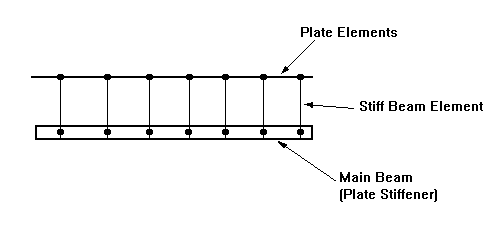
The stiff beams are given zero bending stiffness, but high axial stiffness. The main beam is located at its correct position with the beam offset set to zero. This approach will give a continuous bending moment on the main beam.
For more information please contact us by
e-mail: hsh@iperv.it