 [STRAUS Applications] [STRAUS Specifications] [STRAUS
Users Page] [STRAUS Model Archive] [Technical
Papers and Tips Contents Page] [Technical Articles Contents Page] [Home Page] [Previous
Page] [Next Page]
[STRAUS Applications] [STRAUS Specifications] [STRAUS
Users Page] [STRAUS Model Archive] [Technical
Papers and Tips Contents Page] [Technical Articles Contents Page] [Home Page] [Previous
Page] [Next Page] [STRAUS Applications] [STRAUS Specifications] [STRAUS
Users Page] [STRAUS Model Archive] [Technical
Papers and Tips Contents Page] [Technical Articles Contents Page] [Home Page] [Previous
Page] [Next Page]


The nonlinear geometric solver in STRAUS is capable of analysing the behaviour of mechanisms, similarly to some kinematics packages on the market. The main difficulty we need to overcome when attempting this kind of analysis with finite elements is that a pure mechanism will generate a singular stiffness matrix. There are two ways to deal with this:
1. add a small amount of stiffness somewhere; or
2. use constraint equations to eliminate the singularity
altogether.
The first option works provided we can determine the correct amount of stiffness. Basically if you add too much stiffness, you no longer have a mechanism, and if you add too little stiffness, you may still have a "weak" singularity. You can also generate an ill conditioned matrix using this approach if you have a relatively high stiffness attached to a low stiffness.
The second option is generally preferable. It works in most circumstances, particularly if you can specify a general multi-point constraint as in STRAUS. The multi-point constraints are a convenient way of defining the path for the mechanism.
For some applications, the finite element approach is superior to the traditional kinematic analysis method because with FEA you can model the true stiffness of the linkages, without assuming that they are rigid.
What follows are two simple examples:
1. the movement of a racing car double wishbone suspension;
2. a crane boom being lowered.
The method is sufficiently general that it may be used in 2D as well as 3D, and is suitable for analysing a wide range of structures such as scissor-lift platforms, robotic arms, etc.
EXAMPLE 1 : Four-link suspension including spring.
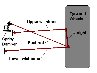
Double wishbone suspension.
The above picture shows a 2D representation of a double wishbone suspension system. This is typical of the setup found on most open-wheeler racing cars and also on some roadgoing sports cars. With this system, the linkage geometry (i.e. lengths, locations of pick-up points, etc.) determines the behaviour of the wheel in "bump" (one wheel moving up and down), "droop" (car body moving up and down) or "roll" (car body rolling due to lateral forces such as going around a corner). The stiffness of the spring determines how much the wheel moves relative to the body.
Using the STRAUS geometric nonlinear solver, we can determine not only the path the wheel will take under a given loading condition, but also how much it will move and the forces in all the members. It would also be possible to model the wheel and tyre, taking into account the friction between the tyre and road and the deformation of the tyre. The ultimate would be to model the system using a nonlinear dynamic solver which could also take into account rates of change and the effect of a damper which has been ignored in this case.
EXAMPLE 2 : Crane boom being lowered
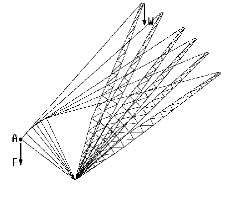
Crane boom.
The above picture shows a crane boom being lowered. The STRAUS nonlinear solver was used to determine the force F required to balance the weight W, over the range of angles considered. The graph below shows the required force as a function of boom angle.
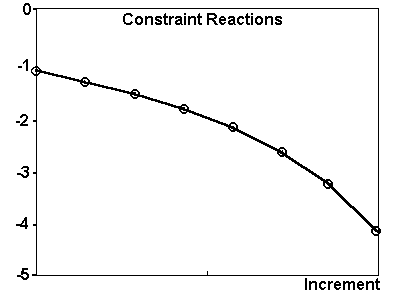
Force vs displacement for boom.
To solve this model, we apply a constraint equation at point A on the model, of the form DY(A)=constant. We use the geometric nonlinear solver to step the displacement and we recover the force F as a by-product.
For more information please contact us by
e-mail: hsh@iperv.it


