 [STRAUS Applications] [STRAUS Specifications] [STRAUS
Users Page] [STRAUS Model Archive] [Technical
Papers and Tips Contents Page] [Technical Articles Contents Page] [Home Page] [Previous
Page] [Next Page]
[STRAUS Applications] [STRAUS Specifications] [STRAUS
Users Page] [STRAUS Model Archive] [Technical
Papers and Tips Contents Page] [Technical Articles Contents Page] [Home Page] [Previous
Page] [Next Page] [STRAUS Applications] [STRAUS Specifications] [STRAUS
Users Page] [STRAUS Model Archive] [Technical
Papers and Tips Contents Page] [Technical Articles Contents Page] [Home Page] [Previous
Page] [Next Page]


We get lots of support questions on the meaning and interpretation of the principal stresses S11, S22 and S33. Questions range from "What are S11, S22, S33 and what do I use them for ?" to "S11 is supposed to be the maximum tensile principal stress but it is negative ?" The following explanation of principal stress should clear up these questions.
In the general three dimensional case there are six components of stress - three normal components Sxx, Syy and Szz and three components of shear stress Sxy, Syz and Sxz. These components of stress lie in three orthogonal planes. The relative magnitude of stresses in 3D is a function of the orientation of these planes. There is a particular direction where the magnitude of all shear stresses is zero. The planes aligned in these directions are the principal planes. The components of normal stress in the three directions are called the principal stresses and are denoted as S11, S22 and S33. These components of stress represent the maximum possible magnitude of tensile and compressive stress at the particular point under consideration.
In the STRAUS output, s11 is the largest value of stress in the algebraic sense and the principal stress S33 is the smallest value of stress. Another way to express this is S33 < S22 < S11 when the magnitude and sign of each principal stress is considered. It must however be clearly understood that the sign of S11 is not necessarily always positive and the sign of S33 is not always negative. In cases of triaxial compression all of the principal stresses will be compressive. The sign of S11 will be negative and the least compressive value of stress. In other cases all components of principal stress can be tensile and hence the sign of S33 can be positive. Similarly the magnitude of S11 is not always greater than the magnitude of S33. Both the sign and magnitude of the principal stresses are considered together to determine which of these becomes S11, S22 and S33.
In the case of a plate element the through thickness stress is zero. This means that the third component of principal stress (S33) is zero and hence the maximum compressive principal stress is S22. The stress S33 is not listed for the plate element.
The classical presentation of principal stress at a point is via Mohr’s circle. This provides a graphical representation of the changing magnitudes of the various components of stress as the orientation of the orthogonal planes is varied. Mohr’s circle for a 2D state of stress is shown in the following figure.
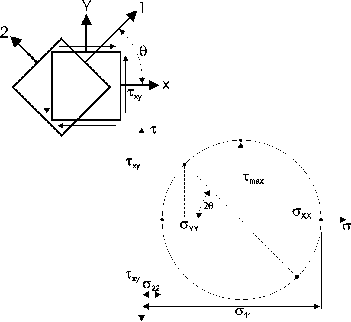
Mohr’s Circle
Mohr’s circle is easy to use. The points at the ends of the diagonal line are defined by a given state of stress in any arbitrary direction. One point has the coordinates (sxx, -txy) , the other point has the coordinates (Syy, txy). These are the stresses at a point in two orthogonal directions.
If a circle is drawn that passes through these two points with the origin lying on the X axis, the two points of intersection between this circle and the X axis are the principal stresses s11 and S22. These points correspond to the principal stresses since the shear stress (txy) is zero.
A transformation of the stress to any arbitrary direction is achieved simply by rotating the diagonal line through an angle 2q (where q is the angle between the X and Y axes and the new transformed axes). The new points of intersection between the diagonal line and the circle represent the transformed state of stress. The angle between the principal directions and the X and Y axes is half the angle between the diagonal line and the X axis.
The principal stresses and angles can also be calculated analytically using simple trigonometry.
So why do we use principal stress ?
The main use of principal stress is to predict failure in a structure which has a complex state of biaxial or triaxial stress. In this application the principal stress is sometimes referred to as the maximum stress criterion.
The use of principal stress as a failure criterion should be restricted to brittle materials such as ceramics. Whilst it can be used in ductile materials such as steel, it is conservative in these applications. The von Mises criterion, which is a function of the three principal stresses, is far more accurate for ductile materials. The von Mises criterion does not however provide any information regarding the sign of the stress. However, in fatigue analysis the sign of the stress is important and thus principal stress is used exclusively for the prediction of fatigue life.
Another important use of principal stress is in plotting vectors of stress for visualising the flow of stress in a structure. STRAUS can produce coloured vector plots of S11 and S22 for the plate elements.
For more information please contact us by
e-mail: hsh@iperv.it


