 [STRAUS Applications] [STRAUS Specifications]
 [STRAUS Users Page] [STRAUS Model Archive] [Technical Papers and Tips Contents Page]
[Technical Articles Contents Page] [Home Page] [Previous Page] [Next Page]
 [STRAUS Applications] [STRAUS Specifications]
[STRAUS Users Page] [STRAUS
Model Archive] [Technical Papers and Tips
Contents Page]
[Technical Articles
Contents Page] [Home Page] [Previous
Page] [Next Page]

STRAUS has a gap element capability in its Linear Static and Non-Linear static solvers.
In STRAUS, the gap element overlays the beam element and is selected by the Beam Type button in the beam property input. After selecting this entry, a pull down menu gives the following options.
| 1. | Normal | A normal beam element |
| 2. | Tens. Only | A Tension only Gap |
| 3. | Comp. Only | A compression only Gap |
| 4. | Tens. Comp. | A gap which can take both compression and tension, but only to a prescribed level. |
The behaviour of each type is described graphically in the figure below.
For each of 2 to 4, an additional load cutoff parameter may be defined; either Maximum Allowable Tension Tmax (type 2) or Maximum Allowable Compression Cmax (type 3) or both (type 4). The figure below shows how these values relate to the gap beams' behaviour.
Once the beam type is selected you may then define an additional parameter, the Cuttoff Type.
Two options are available:
Elast. Plast. Once the specified maximum allowable force is reached, the gap element will continue offering a resistance equal to this value.
Brittle Once the specified maximum allowable force is reached, the gap element will offer no resistance. That is, it is removed from the matrix.
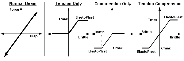
Behaviour of various Gap Beams in STRAUS
The gradients of the Force versus displacement relations shown in the above picture are governed by the stiffness of the beam, namely AE/L.
Example 1: Slab resting on an elastic foundation
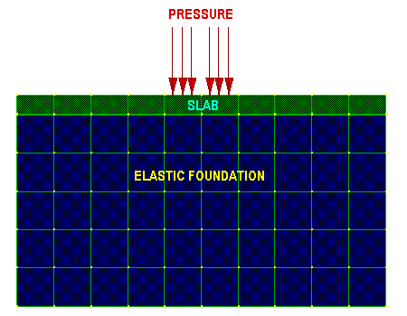
Slab resting on elastic foundation
In this example, a slab is resting on an elastic foundation. A pressure is applieed to the slab.
Because part of the slab may loose contact with its foundation, the two surfaces are connected via compression only Gap beams as shown.
The STRAUS linear static solver is selected and it automatically iterates until all gap beams are either in compression or they have released. The resulting deformation grossly exaggerated is following:
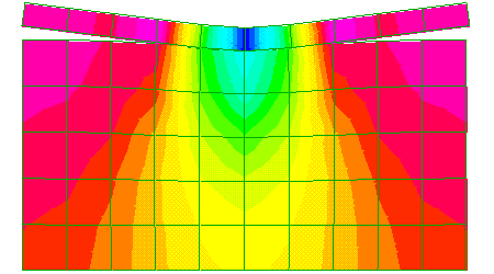
Deformed display, scaled 5%
For this particular example, the following properties are used:
Example 2: Nonlinear Contact Problem
This simulates a pressure activated switch. Here we determine the amount of pressure P, required to cause a given compressive stress at X, as shown in the following figure.
The results of a STRAUS nonlinear analysis are also shown.
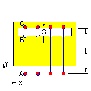
Pressure activated switch. Non linear contact problem
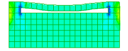
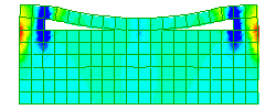
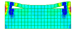
Non Linear Contact problem. Deformed plots scaled 1:1
Modelling Strategy
To achieve this result, we need to combine gap beams with constraint equations. The gap beams themselves are given a pre strain such that the entire gap G is closed.
This means that in the absence of a pressure P, all the gap beams are in tension (so that the gap is pulled shut). Therefore the STRAUS nonlinear solver would eventually release all the beams, since they are compression only. The resulting solution would be one of zero stess and zero strain.
When we apply P, then provided P is large enough to cause the gap to close, some gap beams will be in compression and hence will not be removed. These beams prevent the top of the switch from intruding into the bottom part.
Applying the Pre-Stressing
In order to get the gap to be closed initially, we give the gap beams a temperature T different from the reference valve, Tref and an expansion coefficient a, such that
a(T - Tref)L = -G
where L is the beam length, and G is the gap spacing. That is the gap beams are compressed such that their decrease in length equals G.
Locating the gap beams
The gap beams are located as shown in the non linear contact problem. Note that the beams may be of arbitrary length, provided we apply appropriate constraints.
The constraints
To force the gap beams to remain vertical, we apply constraints of the form
dX(A) = dX(C)
all along the bottom end of the beams.
To make sure that if 'B' and 'C' come into contact they move together, we apply constraints of the form
dY(A) = dY(B)
For this particular problem, the following data is used:
For more information please contact us by
e-mail: hsh@iperv.it