 [STRAUS Applications] [STRAUS Specifications] [STRAUS
Users Page] [STRAUS Model Archive] [Technical
Papers and Tips Contents Pages] [Home Page]
  [STRAUS Applications] [STRAUS Specifications] [STRAUS
Users Page] [STRAUS Model Archive] [Technical
Papers and Tips Contents Pages] [Home Page]

 Isolating Parts of the Structure for Drawing
 Model Checking and Quality Control
 Bandwidth Minimisation and Sorting Option
 Simple Multiple Load Case Problems
 Modelling Shock Problems in STRAUS

We often need to work on some part of the structure and would prefer not to draw all the surrounding elements. Two functions are available to facilitate this:
 CHOOSE function.
This has three states: ALL ON, ALL OFF, SELECT. The
SELECT state allows you to fill a table with the property
type numbers of the elements you wish to display. For
example, to display plate types 2 and 7 only, simply
enter 2 and 7 anywhere in the table. See Chapter 9 in the
STRAUS Manual.  VIEWPORT function.
This is available under the VIEW button or by pressing F11 on the keyboard. It lets you define an area or volume, in the current coordinate system, such that only those nodes and elements which are within the defined area or volume are drawn. See Chapter 9 in the STRAUS Manual.
CHOOSE and VIEWPORT can be used together.

With the increasing use of finite element analysis techniques in more and more sophisticated structures, where the results may not be intuitive, it is important that we as FE users develop checking and quality control procedures and apply these to the analysis tasks that we are undertaking.
A well thought out set of model quality control checks should be capable of detecting most major modelling errors early in the analysis, before expensive decisions have been made or parts are starting to be manufactured. Following are some guidelines to the sorts of checks that should be carried out on all models:
Model Data
Before running any model, especially large ones, the input data should be checked and any modelling assumptions reviewed. This is always best done together with another knowledgable FE user. The following are some suggestions for simple checks that can be carried out:
 |
Check the units of the geometry, the material properties, loadings etc to ensure that they are consistent. |
 |
Check all material properties to ensure that the magnitudes of the moduli, thicknesses etc are correct. |
 |
Check the boundary conditions to ensure that they are representative of the physical support conditions and that they are sufficient to restrict the rigid body motion of the structure. |
 |
Check that adjacent elements are consistent i.e. that each edge of an element is connected to a full edge of other elements and that corner nodes of elements are only connected to corner nodes of other elements, not midside nodes. This is especially important in regions of the mesh that have been locally refined. |
 |
Check that the number of degrees of freedom on elements connected to one another is compatible. For example you should not connect a beam to a QUAD4 plate as the beam element has 6 degrees of freedom and the plate only 5 at each node. Of course this rule can be broken by the experienced analyst if adequate precautions are taken. Carefully check the mesh to ensure that all connected nodes are properly zipped. This can also be checked very effectively in the output display by plotting the mesh with a large displacement scale. |
 |
Check that all the plate elements have their normal Z and preferably their local XY axis systems pointing in the same direction. The Z normal axis is particularly important. As an example consider a model of a pressure vessel. If some of the elements have their normal pointing outward and others pointing inward and we plot a contour of say the +Z surface stresses, we will get a picture showing the stresses on the outer surface of part of the structure and the inner surface of the rest. If some of the elements have the incorrect orientation it is a simple matter to correct this using the flip option in the graphical editor. The orientation of elements can be checked by setting the Type option in the graphical editor or output display to Orientation and redrawing (F3). |
 |
Similarly check the orientation of any beam elements. This is best done by displaying the section of the beam (again from the Type option) however if your model does not use standard section beam properties then you will have to do this by displaying the reference nodes of the beams (set the NREF button to (active). The reference node of the beam and hence the beam local axis system should be checked against the beam local axis system assumed in the input data for I11, I22 etc. |
Solution LOG File
Before looking at the results of a solution the LOG file generated by the solver should be examined in its entirety. The sorts of things that we need to look for are as follows:
 |
Check that the singularities (suppressed drilling freedoms) listed are consistent with the types of elements in the model and the boundary conditions applied. |
 |
Check the summation of the forces produced by the solver. Does this equal the applied loads. Note that there may be some minor difference here if some loads are applied to nodes that have fixed boundary conditions since the load applied to these nodes is not included in the summation. Generally though, the forces and moments listed, must be in equilibrium with the applied loads including forces, moments, pressures, inertia loads etc. |
 |
Check for warning messages. Ensure that you understand all warning messages and the implications of these on the results. Typical warnings are for warped elements, elements with acute internal angles etc. You can use the View ASCII File module to search for warning messages. |
Results
It is good practice to question or even distrust the results from any FE program or model until you are sure that they make sense. Checking results is as much experience as a set of rigid rules but the following simple guidelines should give you an idea of the areas in which to start:
 |
Check that the sum of the reactions equals the applied loads. |
 |
Check the displacements at the supports or symmetry conditions to ensure that the boundary conditions have worked correctly (i.e. that the displacements are zero in the correct directions). |
 |
At a few locations where the stresses can be calculated using simple equations, do a 'back of the envelope calculation' to verify the output stresses. Again using the example of a pressure vessel, the stresses can be calculated approximately from the classic PR/2T type calculations for hoop and axial stress. Ensure that the stresses are within a few percent of these. Obviously these simple equations cannot calculate the stresses at the ends of the vessel where the stress state is more complex due to bending etc, but this is the reason we use finite elements. |
 |
Similarly check the magnitude of the displacements at some point where the results are easily checked by a simple calculation. Just because the stresses are correct does not necessarily guarantee that the deflections are also correct. If the modulus is out by a factor of 1000, say, then the deflections would be wrong but in a linear static analysis the stresses would be correct. |
 |
Check the deflected shape of the structure and ensure that this is consistent with the stiffness and geometry of the structure, the loads and boundary conditions. |
It would be considered good practice, and in fact may be required under some quality systems, to formalise these checks and create a simple check list with provision for indicating that a particular model has been checked.
If you are new to finite element analysis or are experienced but conducting a new type of analysis with which you are not familiar, then there are some additional checks that you should be doing. These involve the running of simple benchmark tests. The idea is to make several simple models that are representative, in a very simplistic way, of the real structure you are interested in. The answers for these models should be readily calculated from elementary mechanics or should be published experimental test data. The idea here is to hone your modelling methods, to make sure you know what all the input data required means, to make sure that your results are correct and that you know how to interpret them. Even experienced FE analysts employ simple models of this type if they are not absolutely confident with the techniques to be used in a particular application.

One very important option in the Solver Panels is the Sorting option. This is for selecting the bandwidth minimisation strategy. STRAUS offers two algoriths: one geometrically based (GEOM) and another element connection based (TREE). These attempt to reduce the RAM and disk space requirements. We usually discover that new users do little experimentation with the sorting option. For a large model, or one being run using the nonlinear solver, it is very useful to spend a few minutes checking each option to find the best one. The TREE option also allows the input of a Tree Start Node. The idea is that a tree-like structure of all the connections is generated. It turns out that the selection of the node for the root of the tree can have a significant effect on the resulting matrix. The mesh in the following figure was checked using the GEOM sorting option and the TREE option with two different starting points.
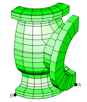
| METHOD | RAM (MB) | DISK (MB) |
|---|---|---|
| GEOM | 6.24 | 20.4 |
| TREE @ A | 4.60 | 20.5 |
| TREE @ B | 1.60 | 15.2 |
Also shown below are the actual matrices generated by each option. The dark regions indicate non zero entries in the matrix. The aim of any bandwidth minimiser is to eliminate all peaks and "flatten" the matrix as much as possible. The more "diagonal" a matrix is, the faster it will solve.
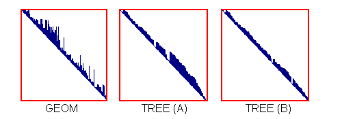
The default sorting option is GEOM. With this method, STRAUS looks for a dominant length direction in the global X-Y-Z system and renumbers the nodes in that direction. It is particularly effective for structures of the type shown below (the blade), provided the main length direction is parallel to one of the global axes. For models like an impeller,the TREE option is generally better.
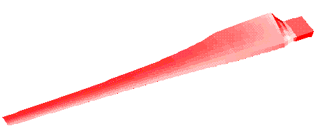
Structure suited to the GEOM sorting.
For large structures, it is very worthwhile to test both
methods to see which one gives the lower memory (RAM) and disk
space requirements (you can stop the solver at any time simply by
pressing <Cntrl>C or <Cntrl><Break>). The
following STRAUS solver message:
Minimum RAM for InCore Solve = ???
is significant in terms of how long a solution will take.
The value given by this STRAUS message is probably the most significant in terms of how long the solution will actually take, particulary for linear static analyses. The value tells you how much physical RAM (not disk space) is required by the solver such that the matrix can be reduced by a single pass through the file.
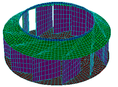
Structures suited to TREE sorting.
If the required amount of RAM is not available, then the solution will still proceed (provided there is sufficient disk space available), but generally with a significantly increased solution time. In general you should aim to reduce the RAM requirement, even at the expense of increasing the Disk Space requirements.
When performing these checks, bear in mind that STRAUS does not necessarily "see" the total amount of RAM your PC has installed. For example, on a PC with 8MB, the breakdown is typically as follows:
| Memory Usage | Amount |
|---|---|
| Conventional memory not used by STRAUS because STRND6 runs in protected mode | 1 MB |
| SMARTDRV.EXE (if loaded) | Up to 2 MB |
| Program space for loading the STRAUS solver and its associated memory requirements (stack space, etc.) | Up to 1 MB |
| Amount of memory actually available to the STRAUS solver | Remaining 4 MB |

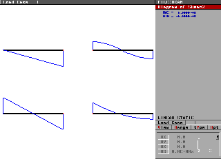
When modelling simple structures with multiple load cases it is sometimes useful to copy the model in the graphical editor to produce one mesh for each of the load cases. Each of the load cases is then applied to one of the meshes, all as load case 1 as far as STRAUS is concerned. These 'separate' models are then run as a single model. The advantage of this technique is in postprocessing. Basically the results of all the load cases can be viewed togther on the screen at one time. This is a technique we use regularly for testing and it is also used by some users.
Note that for large structures, you can still view all the load cases at once by using the "Window" option (F12).
In many of the solver panels there is an option 'Suppress
Drilling Freedoms - YES/NO'. Our experience is that many new
users do not understand the concept of drilling freedoms.
Basically the formulation for the TRIA3, TRIA6, QUAD4, QUAD4 CST and QUAD8 plate elements only includes 5 degrees of freedom at each of the nodes. This is normal practice in conventional plate shell theory (refer to Timoshenko's "Theory of Plates and Shells"). The finite element method in general includes a full six degrees of freedom for each node (DX, DY, DZ, RX, RY, RZ). The only plate element formulation that includes all six degrees of freedom within STRAUS, is the QUAD4 Thin Shell.
Thus the 5 dof plate element formulations do not provide any stiffness in one direction - rotation about the axis normal to the plate. This is called the drilling freedom. It has been found that this degree of freedom is redundant in formulating equations that describe the behaviour of general plate shell structures. Thus it is simply ommitted from the classical formulations to reduce the complexity of the problem. Unfortunately this creates problems with numerical analysis.
If you can imagine building a model of a flat plate out of QUAD4 plate elements (say), the elements will not provide any stiffness to prevent rotation of each node about an axis normal to the plate. Thus the nodes are free in this rotational direction. This is called a singularity. If we tried to solve the problem without taking any special precautions, the global stiffness matrix would end up with zeros on the diagonal due to these free components of rotation and the Gaussian matrix solution would fail.
In order to solve this problem we must use a procedure to suppress these singularities. Basically STRAUS checks each of the nodes in the model to ensure that they have stiffness in each of the 6 global directions. If a node is found that has zero stiffness (actually less than some user set threshold - see Default Solver Options) STRAUS then determines whether this is in a direction normal to a plate or some other direction. If the singularity is in some other direction then STRAUS assumes that the problem is far more serious and terminates the solution. If the singularity is normal to a plate then it is assumed to be a drilling freedom singularity. STRAUS then adds a small amount of stiffness to the matrix to avoid the singularity and to allow the solution to proceed. The amount of stiffness added is small and not sufficient to influence the results of the analysis. The amount of stiffness added can be controlled by the user via the default solver options. Normally the default will be sufficient for most problems.
So the option in the solver panels, 'Suppress Drilling Freedoms' is simply asking the user whether or not the solver should execute this drilling freedom checking and supression procedure.
In general this option should be set to YES for all plate models. However sometimes models will run without suppression of the freedom conditions. If the plates connecting to a particular node all meet at different angles then enough stiffness will be generated in the transformation processes to suppress any drilling singularity. In other cases enough numerical round off may be present in the element assembly process to suppress the drilling singularity.

Recently we have had a number of users enquire about the use of STRAUS in modelling shock problems. It seems like more and more design specifications require shock testing as part of the design validation. Traditionally shock testing was carried out experimentally using a shock or shaker table. However in many cases it makes good sense to perform a shock analysis on the structure before testing to ensure that experimental shock test will be passed on the first attempt.
Depending on the exact nature of the test required a shock analysis can be performed in STRAUS using either the transient or spectral solvers. The transient solver can provide a full time history of the reponse of the structure to the shock. The transient solver is suited to analysis of drop tests and tests where a pulse of load is applied to the structure however it cannot be used to model the common base acceleration problems. The spectral solver is an aproximate method that is ideally suited to the majority of shock problems where a short pulse of load or acceleration is applied to the structure. The spectral solver will only yield the maximum response of the structure, it cannot calculate the full time history of the response.
The are basically three types of shock test:
Tests 1 and 2 are by far the most common. Following is a discussion of the methods used to model each of these test types.
Often design specifications require a component to survive, without damage, a drop from a certain height. This sort of problem is best handled using the transient dynamics solver. If a structure is dropped from a given height we can readily calculate the velocity at the instant before impact using the equation:
V is equal to the square root of 2as
where:
s = drop height (m)
a = gravitational acceleration = 9.81 m/s2.
Freedom conditions are applied to the model at the points where it will contact the ground when dropped. The transient solver is run using an initial velocity equal to the calculated impact velocity. Impact problems will require the use of a small time step due to the rapid rates of loading. It is important to use a time step equal to approximately 1/100th of the period of the mode of the structure that will be excited during the impact. If the time step is too large, the analysis will not capture the full reponse of the structure. In particular the higher frequency components of the reponse will be missed.
Note that this method is valid only for modelling the response of the structure up to the point at which the structure begins to bounce off the impact surface. Past this point, a nonlinear transient dynamic analysis is required.
Spectral analysis is an approximate method that allows the calculation of the peak response, of a specified loading. There are four different spectra types that can be used with the STRAUS spectral solver. These are the seismic acceleration, seismic velocity, seismic displacement and force spectrum methods. The first three spectra are assumed to excite the structure by movement of the base (i.e. the points where freedoms are applied). The force spectrum applies a more general spectral loading at any point on the structure. All the different spectra are used in a similar manner. The acceleration response spectra is used for most shock problems and will be considered here.
There are three factors which are combined to give the spectral acceleration applied to the base of the structure: these are the global acceleration applied to the model, spectral value and the direction factors in the solver panel. For the acceleration response spectrum the spectral acceleration applied to the model is:
Spectral acceleration = global acceleration x direction factor x spectral value
The spectral value is a function of the frequency of the structure. This is defined by a spectral curve in the Tables module.
The components of the direction vector are simply factors that multiply the applied loads. They define the direction of the seismic acceleration and may be either normalised or non-normalised.
In shock problems using the method outlined here the global acceleration x direction vector defines the maximum amplitude of the applied acceleration. The spectral value is a factor that defines the effect of the acceleration on the different modes of vibration of the structure.
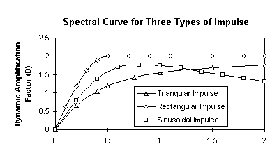
As mentioned, the spectral value is defined by a spectral curve input in the Tables module and is a function of the frequency of the structure. This is also called the Dynamic Amplification Factor by many texts on dynamics. This factor defines a response ratio between the dynamic response and an equivalent static response when the structure is loaded with the peak acceleration. Basically the response of the structure to a loading will depend on the ratio of the frequency of load application and the natural frequencies of the structure. For a loading frequency much higher than the dominant frequency of the structure, the reponse of the structure will in general be less than the response from an equivalent static acceleration.
In all the impact analyses that we have been involved with the structure is loaded with a very short pulse of high acceleration - at a higher frequency than the frequencies of the structure that are excited by the impulse. In these cases the response of the structure will be considerably less than that which would result if a steady acceleration were applied equal to the peak acceleration during the impact.
The calculation of the spectral value or amplification factor is covered in texts such as Clough and Penzien 'Dynamics of Structures'. The following graph shows the spectral value as a function of the frequency ratio for a number of common impulse loading waveforms. Equations for these curves are given in Clough and Penzien. The curves are graphed with the X axis as frequency ratio (frequency of structure divided by frequency of load). This is the normal way of presenting this sort of data as it is independent of the frequency of the load application and the frequency of the structure. STRAUS requires the spectral table to be input with an X axis of frequency of the structure. Thus the X axis of the gragh below needs to be converted to frequency of structure. This is readily done once the frequency of the load application is known.
For simple examples where one mode of the structure dominates the response, a constant value of spectral acceleration applicable to the dominant frequency can be used (i.e. a table with two points defining a constant spectral value).
For a more general problem with say 20 frequencies contributing to the response, a spectral curve is required that covers the entire frequency range and the spectral analysis should include all of these frequencies (enter the number of frequencies to be included in the solver panel). A spectral value will then be calculated for each of the frequencies and used to excite the corresponding mode. The responses for each of the modes are then combined to get the total response using either the CQC or SRSS methods (see Clough or the STRAUS release notes for details of these).
If the spectral curves shown in the above graph are not
applicable to a particular problem you can calculate the spectral
curve using some simple single degree of freedom models in
STRAUS. Basically the procedure is as follows:
 |
Establish the loading input ie. magnitude, period and shape of load vs time curve. |
 |
Establish the frequency range of interest ie. check which modes of the structure will contribute to the response when the loading is applied. |
 |
For each of the frequencies of interest, f, construct a simple single degree of freedom model such that the simple model has a fundamental frequency equal to f (f= square root of k/m). Normally this model would be a mass on a spring (beam element). If the spectral curve for an acceleration response is being determined the loading will be applied as an acceleration. |
 |
For each of the models carry out a full time history transient solution with the loading defined by a load vs time table. The loading in all cases should be the input established in step 1. From the transient response analysis determine the peak acceleration response. This is the spectral acceleration required by STRAUS. |
 |
The spectral value used in the above method is the ratio between this calculated spectral acceleration and the applied peak acceleration. |
 |
Plot a graph of spectral acceleration or spectral value vs the frequency of the structure and fit a curve through this. This is the spectral curve. |
When an impact loading is applied to a structure in some general manner such as the structure being hit at some point, both the transient and spectral solvers can be used. In both cases a time history of the impact force must be assumed.
As discussed above the transient solver can calculate the full time history of the reponse of the structure to the impact. In this case the maximum amplitude of the loading is applied to the structure. The time history of this load is defined by the input of a load vs time table. This table is linked to the appropriate load case in the transient solver panel. The transient solver is run, once again using a very small time step to capture the response.
An approximate but faster method for this sort of analysis is to use the Spectral Solver with a load spectra. The procedure is very similar to that discussed above for base acceleration problems except that the solver assumes that the loading is applied at some point other than the base. The spectra is derived as described above and in most cases can use the standard spectra defined in Clough. The amplitude of load would be input as a point force in most cases at the point of application on the structure. The spectral curve will define the spectral value as a function of frequency.
For more information please contact us by
e-mail: hsh@iperv.it